Flow Measurement Instruments
- Low Flow Liquid Meters
- Low Flow Gas Meters
- Duct Flow Meters for Air & Gas
- Low Flow Controller
- MaxExtractor Extraction Monitor
- Multi-Variable Process Meter
- Bidirectional Flow Meters
- RheoVac® Multisensor Flow Monitors
- Flow Switches
- Custom Process Measurement
- Instruments for Hazardous Locations
- Electronics Options
Bidirectional Flow Meters
Bidirectional flow lines are not very common in most process plants, but if they are needed, they always present difficulties for process and instrumentation designers. For bidirectional flow, the piping scheme uses the same line to accomplish delivery and/or control functions for flows moving in opposite directions (forward or reverse flow), depending upon the process conditions and objectives.
The measurement of unidirectional flow rate is well-understood and possible with all types of flow technologies. However, most flow technologies cannot accurately measure bidirectional flow. This may result in process interruptions and/or measurement inaccuracies that can significantly affect the production and profitability of a plant. For this reason, Bionetics has designed the Rheotherm Model 213 Bidirectional Flow Meter for liquids and gases.
Bidirectional Flow Measurement
Measurement of dielectric fluid through underground cables is an example of an application that requires bidirectional measurement. 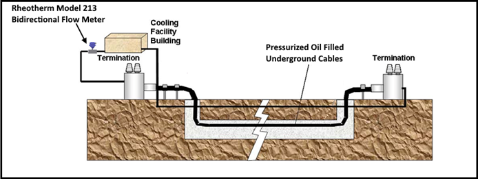 Underground electric cables are injected with dielectric fluids from utility pumping and circulating plants to dissipate heat generated by high voltage power lines.
 What Can We Measure?
The Bionetics Rheotherm Model 213 Bidirectional Flow Meter provides a solution in these applications, measuring extremely low flow rates, as low as 0.2 cc/min, while providing accurate results. Our Rheotherm flow meters have no moving parts and require no regular maintenance to maintain calibration accuracy. Rheotherm flow meters may be constructed from several wetted materials, resulting in chemical compatibility with most chemicals.
Contact us using the form on this page to discuss your flow measurement application. You can also download and complete the Flow Application Data Sheet and email it to us at sales-flow@bionetics.com.
How Are They Installed?
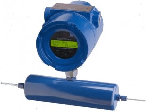
Rheotherm flow meters incorporate in-line flow sensors typically installed with standard tube fittings, but optionally available with flanges, sanitary fittings, etc. With some models the electronics are integral to the sensor. Other models have a separate electronics enclosure that can be installed up to 200 feet from the sensor. Electronics Options
How Do They Work?
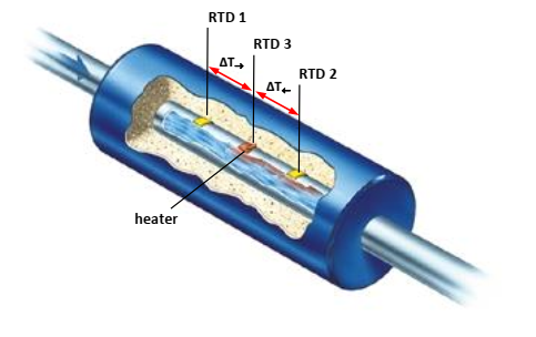 The Rheotherm Model 213 Bidirectional Flow Meter uses a straight-through flow tube with a series of RTDs attached to the outside of the flow tube. The two unheated RTDs measure the fluid temperature and the third RTD measures the temperature of a constant low-power heater which is cooled by the flowing fluid through the tube. The temperature differential between the heated and unheated RTDs provides the primary flow signal.
Nothing touches the fluid except the flow tube wall, and there are no mechanical parts to wear, stick or break. More on Method of Operation(PDF)
How Do I Get One?
Contact one of our flow application specialists using the form on this page to configure a flow meter tailored to your application. You can also visit our Contact Us page for telephone, fax and email information.
- No moving parts
- Exclusive inline TU sensor
- Advanced signal processing electronics
- Field adjustable
- Maintenance-free
- Easy installation
- Choice of wetted materials
- Long-term reliability
| Standard | Options | |
| Temperature | Process: 0 – 140°F (-18 – 60°C) Environment: 0 – 120°F (-18 – 50°C) |
-20 – 350°F (-30 – 175°C) |
| Pressure | 0 – 1,000 PSI | Up to 30,000 PSI |
| Line Sizes (flow range dependent) |
1/16”; 1/8”; 3/16”; 1/4”; 3/8”; 1/2”: 5/8”; 3/4”; 1” |
Other sizes via fittings/adapters |
| Process Connection | Plain tube stubs suitable for compression fittings | – MNPT: – Tri-Clover (Sanitary); – SS Flange (1/2″ – 2″); Most other fittings available |
| Wetted Material | 316 SS | – Hastelloy C-276®; – Monel®; – Alloy 20; – Titanium; – Tantalum; – Inconel |
| Display | 2 X16 backlit LCD with selectable display of: – Mass/volume flow rate – temperature – total accumulated flow |
|
| Standard | Options | |
| Enclosure | Sensor: PVC Integrated Electronics: NEMA 4X Cast Aluminum Remote Electronics: NEMA 4 |
Sensor: Stainless steel Remote electronics: – Stainless steel – NEMA 7 Explosion-proof |
| Hazardous Environment | Integrated electronics FM-Approved for: – Class I, Div. 1, Groups B,C,D – Class I, Zone 1, IIB+H2 (US) – Class II, Div. 1, Groups E, F, G – Class III, Div. 1 |
|
| Outputs | 4 – 20 mA (flow rate) or Serial Burst with Flow Rate, Totalizer, and Fluid Temperature | – 0 – 10 or 0 – 5 VDC; – HART (4-20 mA) ; |
| Input Power | 24 VDC ±4V (200 mA – blind unit; 300 mA w/display option) |
110/230 VAC ±10V |
|
|
||||
|
|
||||
|
|
|
||||
|
|
|


Need More Info?